
Views: 0 Author: Site Editor Publish Time: 2026-08-19 Origin: Site
Discovering structural weak points during a thermoforming production run is highly frustrating. You might also notice aesthetic inconsistencies across your parts. Unplanned material thinning directly threatens your product viability. It jeopardizes strict regulatory compliance. It severely damages your bottom-line profitability. Some degree of material stretching is inherent to the thermoforming process. However, unpredictable or severe uneven thickness always points to systemic failures. These issues usually stem from poor tooling, bad heating, or weak process control. You cannot afford to ignore these manufacturing defects.
This guide breaks down the core engineering root causes of material inconsistencies. We provide a rigorous framework for evaluating effective solutions. You will learn how to mitigate production risks immediately. Furthermore, we show you how to select a manufacturing partner capable of maintaining strict tolerances. Mastering these principles ensures your parts meet functional requirements every single time.
Tooling is the foundation: Inadequate mold design—specifically the absence of plug assists or improper draft angles—is the primary driver of uneven wall thickness.
Thermal management dictates distribution: Zonal temperature control and understanding a specific polymer’s sag point are non-negotiable for consistent sheet stretching.
The draw ratio defines risk: Deep-draw parts require advanced process intervention to prevent excessive thinning at the base and corners.
Evaluation requires evidence: A qualified thermoforming partner should provide transparent data on their tooling validation, thermal mapping capabilities, and automated thickness inspection protocols.
Engineers often view material thinning as a mere technical defect. You must shift your focus toward its severe commercial consequences. Minor dimensional deviations quickly cascade into massive financial losses. They ruin client relationships and destroy brand trust. Understanding these business impacts helps justify investments in better machinery and superior tooling.
Localized thinning severely compromises load-bearing capacities. It drastically reduces overall impact resistance. Critical barrier properties also degrade significantly. These factors are absolute requirements in medical device packaging. They are equally vital for aerospace components. Parts fail entirely when they cannot support intended physical loads. A thin corner on a shipping tray causes product damage during transit. A compromised medical blister pack leads to sterility failures. You must maintain consistent thickness to ensure reliable mechanical performance. End-users rely on your components to perform flawlessly under stress.
Inconsistent material specs introduce massive compliance dangers. Failing rigorous industry standards carries heavy penalties. The FDA mandates strict material tolerances for medical packaging. The ISO requires documented consistency across production runs. The FAA demands exact structural integrity for aviation interiors. Uneven thickness triggers audit failures. It forces devastating product recalls. Regulators will halt your production if you cannot prove process stability. Documenting uniform wall thickness is a mandatory regulatory defense. Your quality assurance team needs reliable data to pass these audits successfully.
Troubleshooting defects mid-production actively destroys your profit margins. Wasted resin adds up incredibly fast. Machine downtime costs thousands of dollars per hour. You also face delayed time-to-market scenarios. High scrap rates indicate an out-of-control manufacturing process. Operators tweaking settings blindly only make the problem worse. Scrapping poorly formed parts forces you to buy more raw materials. You consume more energy running replacement cycles. This inefficiency drains resources and frustrates production managers. Getting the thickness right on the first try is highly lucrative.
Identifying the root cause of defects requires a systematic engineering approach. Random adjustments rarely solve persistent material distribution problems. You must understand the physics of heated polymers. Addressing uneven thickness in thermoforming requires understanding how heat, tooling, and timing interact. Let us examine the primary culprits behind these failures.
Plastic stretches most where it is hottest. This is a fundamental law of thermoforming. Uneven heating elements cause major problems. Ambient drafts also cool the sheet unpredictably. This forces the plastic to stretch unevenly across the mold. Areas retaining excess heat become dangerously thin. Cooler sections resist stretching and remain overly thick. It ruins the final part dimensions.
Older or poorly maintained ovens lack critical micro-zonal control. They cannot profile complex parts accurately. Modern manufacturing requires distinct temperature zones. You need precise control over every square inch of the heating element. Without zonal management, the thermal gradient fluctuates wildly. Operators cannot compensate for ambient factory temperature shifts. This leads to inconsistent sheet stretching from morning to night.
The draw ratio heavily defines your thinning risk. It compares the depth of the part against its surface area. A high draw ratio naturally causes material to thin. The plastic travels far into the mold cavity. It stretches continuously as it moves. Deeper cavities pull more material from the surrounding areas. If the design ignores this reality, failure is imminent.
Using straight vacuum forming for deep-draw parts is highly problematic. It practically guarantees excessively thin corners and bases. The material simply runs out of volume. It locks onto the upper sidewalls too early. The remaining plastic stretches too far to reach the bottom. Mechanical assistance becomes strictly necessary here. Upgrading your tooling strategy is the only viable fix.
Applying the vacuum too early disrupts uniform distribution. Applying it too late causes the same issue. The timing must perfectly match the material’s viscoelastic state. Plastic requires a specific window of pliability to flow properly. If you trigger the vacuum prematurely, the plastic stops moving. It fails to reach the deepest mold sections evenly.
Rapid, uncontrolled vacuum application causes significant damage. It "locks" the plastic onto the tooling surface prematurely. Friction stops the material from sliding. The remaining stretch zones thin out aggressively. They bear the entire stretching burden alone. You need precise, stage-based vacuum controls. Programmable logic controllers (PLCs) help eliminate these timing failures entirely.
You can overcome material flow challenges with modern engineering interventions. Transitioning from basic methods to advanced techniques stabilizes your output. Implementing these solutions requires upfront investment. However, they drastically reduce scrap and guarantee dimensional stability.
A mechanical plug solves deep-draw thinning issues effectively. It pushes material into the mold cavity physically. This action happens right before you apply the vacuum. It distributes the plastic mass deeply into the mold. The material easily reaches bottom corners and tight radii. The plug does the heavy lifting for the plastic sheet. It prevents the sidewalls from thinning out prematurely.
Plug material selection is incredibly important for success. Syntactic foam is the industry standard for these plugs. It prevents premature cooling of the plastic sheet. Solid metal plugs conduct heat away too quickly. This chilling effect creates unsightly stretch marks. Foam plugs insulate the hot plastic upon contact. They allow the material to keep flowing smoothly.
Grid strain analysis provides incredible visual data. You print a grid pattern on prototype plastic sheets. The sheet enters the forming phase normally. Afterward, you measure how the grid squares distorted. This mathematically tracks material flow across the geometry. It shows exactly where the plastic stretches too much. It removes all guesswork from the troubleshooting process.
This data drives critical mold design tweaks immediately. You can add strategic radii to sharp corners. You can optimize draft angles for better material release. It also highlights where mold temperature control fails. Adding specific water-cooling channels regulates tooling temperatures. Advanced mold design directly dictates your final part quality.
Thermal mapping offers precise control over flow resistance. You program custom heat profiles across the oven matrix. You apply less heat to areas stretching first. You apply more heat to areas traveling further. This artificially controls how the plastic behaves during forming. It forces thicker sections to stretch more easily. It protects vulnerable areas from over-stretching.
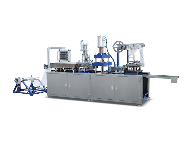
Using an Advanced High-Efficiency Thermoforming Machine enables this precision. Such equipment features independent quartz or ceramic heaters. The control software saves specific recipes for different polymers. You can map out a perfect thermal profile repeatedly. This technology eliminates operator guesswork entirely.
Table 1: Process Interventions and Expected Quality Outcomes
Intervention Type | Implementation Method | Primary Quality Outcome |
|---|---|---|
Plug-Assist Technology | Using syntactic foam plugs to pre-stretch plastic. | Maintains uniform thickness in deep corners and bases. |
Multi-Zone Heating | Programming distinct oven heater zones. | Prevents localized material sag and unpredictable thinning. |
Grid Strain Analysis | Printing grid lines to track material deformation. | Identifies exact friction points for mold geometry correction. |
Active Mold Cooling | Routing water channels within the aluminum tooling. | Stabilizes cycle times and prevents progressive part distortion. |
You must audit a vendor’s technical ability before signing any contract. Preventing uneven thickness starts during the vendor selection phase. Do not rely on their marketing materials alone. Demand transparent evidence of their engineering capabilities. A strong partner openly shares their quality assurance data.
Ask if they design tooling entirely in-house. Outsourced tooling often lacks tight integration with specific machines. In-house teams iterate designs much faster. Question their specific approach to plug-assist integration. Ask how they route thermal fluids within the mold structure. Superior tooling directly translates to superior parts. Poor tooling guarantees inconsistent wall thickness. You need experts who understand complex draw ratios deeply.
Reject partners relying solely on manual visual inspection. Human eyes cannot detect minute thickness deviations accurately. Require definitive proof of automated inspection methods. Ask for reports from ultrasonic thickness gauges. Demand Coordinate Measuring Machine (CMM) data for complex geometries. Rigorous First Article Inspection (FAI) is absolutely non-negotiable. They must prove the part meets your dimensional specifications perfectly. Evidence-based quality control separates true professionals from amateurs.
Prototyping success does not guarantee production success. Ask if their validated process window holds true long-term. Can they guarantee consistency during a 10,000-unit run? Heat builds up in molds over hundreds of cycles. The factory environment changes throughout the day. Look for automated, closed-loop machine controls. Manual operator adjustments introduce massive variability. Scalability requires data-driven automation, not human guesswork.
Moving from a few prototypes to full-scale production introduces hidden risks. You must anticipate these shifts early. Process parameters that work for ten parts often fail for ten thousand. Managing this transition requires discipline and proactive engineering.
Prototypes often behave differently than scaled production runs. Heat buildup in the mold over time alters material flow. Aluminum tooling absorbs heat during rapid cycling. If the cooling channels are inadequate, the mold runs too hot. A hot mold changes how the plastic shrinks and stretches. You must validate the cooling system during pilot runs. Continuous monitoring prevents thermal runaway in the tooling.
Never assume nominal starting sheet thickness equals final part thickness. Starting with a thicker sheet to compensate for thinning is a terrible strategy. It is a costly and inefficient band-aid. It is not a root-cause solution. Thicker sheets waste expensive resin. They demand longer heating times. They require longer cooling cycles. This slows down production significantly. Furthermore, non-stretched areas become excessively thick. They will fall out of your tolerance specifications. Always optimize the process, do not just thicken the raw material.
Take decisive action to secure your production quality. Follow these strict implementation guidelines:
Establish explicitly defined minimum thickness tolerances in your initial Request for Quote (RFQ).
Demand a detailed Process Capability Index (Cpk) report during the pilot run. Aim for a Cpk greater than 1.33.
Specify the required inspection locations on your engineering drawings clearly.
Conduct an on-site audit of the vendor’s thermal management systems.
Uneven thickness in thermoforming is not an unavoidable law of physics. It is a highly solvable engineering challenge. The root causes lie in tooling design, thermal management, and process control. You can eliminate these defects by upgrading your manufacturing approach. Implementing plug assists and multi-zone heating transforms your output completely.
Successful production requires moving beyond basic, outdated vacuum forming methods. You must embrace precision, data-driven manufacturing. Relying on grid strain analysis and rigorous CMM inspections guarantees structural integrity. Stop accepting high scrap rates as a normal cost of doing business.
Schedule a comprehensive engineering review of your current thermoformed components today. Submit your CAD files for a strict manufacturability assessment. Request a quote from a partner who demonstrates proven quality control infrastructure. Prioritize evidence-based manufacturing to protect your brand and your bottom line.
A: There is no universal standard; it depends entirely on the application and draw ratio. However, a competent manufacturer should be able to maintain specific minimums in critical zones. They can often keep variations within ±10% to ±20% of the targeted post-form thickness by utilizing precision tooling and advanced controls.
A: The draw ratio is the relationship between the surface area of the original sheet and the surface area of the molded part. Higher ratios mean the same volume of plastic must cover more area. This inherently reduces thickness. Ratios over 2:1 typically require plug assists to prevent failure.
A: Rarely. While it may ensure the thinnest spots meet minimum requirements, it increases material costs unnecessarily. It also prolongs heating and cooling cycles. It often causes the non-stretched areas to be excessively thick and out of tolerance. The correct solution is always process and tooling optimization.
A: Pressure forming utilizes compressed air on the non-mold side in addition to a vacuum. This allows for crisper details and sharp corners. While it helps definition, preventing uneven thickness in both processes relies heavily on temperature profiling and plug-assist techniques rather than just the pressure differential.


