
Views: 0 Author: Site Editor Publish Time: 2026-09-22 Origin: Site
Minor miscalculations in mold engineering carry heavy penalties. They directly translate into high scrap rates, webbing defects, and blown cycle times. Successful manufacturing demands more than just heating a plastic sheet. It requires precise control over air evacuation and thermal management. If trapped air remains in the cavity, parts fail inspection. If temperatures fluctuate, production grinds to a halt. We must understand how these mechanisms work together. This article breaks down how these critical tooling elements interact during production. We explain how they dictate your overall output quality. You will learn specific criteria to evaluate when sourcing new molds for your production lines.
Poor tooling design destroys production margins rapidly. When tools lack proper engineering, manufacturing cycles slow down. Operators often compensate by spraying excess mold release agents. This creates severe residue buildup over time. The residue transfers onto finished parts. Wall thicknesses become inconsistent. The structural integrity fails entirely. You lose expensive raw materials. You also waste valuable machine hours.
Atmospheric pressure acts as the primary driving force in this process. It pushes the heated sheet into the mold cavities. Trapped air acts as an invisible, stubborn barrier. It pushes back against the molten plastic. Uneven tool temperatures freeze the material prematurely. This disrupts uniform stretching across complex geometries. Proper plastic forming mold quality hinges entirely on managing these two physical forces.
High-quality tools achieve two critical functions simultaneously. They execute rapid, uniform air evacuation. They also ensure rapid, uniform heat extraction. You cannot sacrifice structural tool strength to achieve these goals. Success requires engineering a perfect balance. Production teams must prioritize these elements before finalizing any tooling purchase.
Inadequate evacuation leaves large air pockets trapped inside the cavity. The hot plastic cannot touch the cold tooling surface. This barrier causes incomplete forming. It creates severe webbing defects, particularly in deep draws. Corners lose their sharp definition. The packaging looks sloppy and unprofessional. Complex geometric shapes suffer the highest defect rates.
We must balance hole size against cosmetic requirements. Large holes evacuate air quickly. However, they leave raised bumps called witness marks on the plastic. Thinner materials require micro-venting. Engineers usually specify extremely small diameters for these films. You must place vents strategically across the tool. Deep cavities need maximum air flow. Sharp corners require intensive evacuation paths. Textured areas also demand careful attention to prevent air entrapment. Effective thermoforming mold venting remains a delicate balancing act.
Drilled holes represent the industry standard. They cost less to manufacture but have density limits. Porous aluminum inserts offer an excellent alternative. They allow air to pass directly through the solid metal. This technique eliminates visible witness marks entirely. Slot venting uses narrow gaps machined between separate tool blocks. Each method scales differently in high-volume production environments.
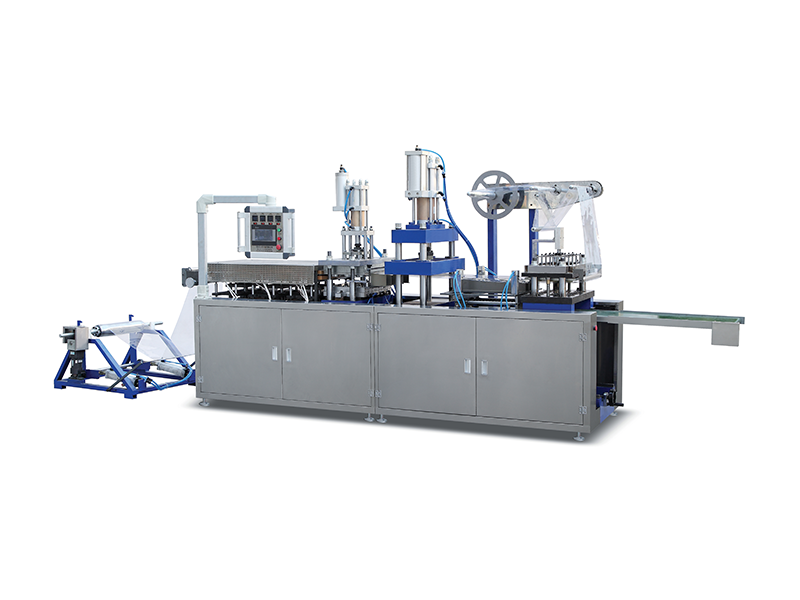
Uneven cooling causes severe differential shrinkage. Some sections of the plastic freeze faster than others. This locks residual internal stress inside the polymer chains. Upon demolding, the part warps uncontrollably. It loses dimensional stability instantly. Assembly lines reject these warped parts later in the process. A highly strategic approach to thermoforming mold cooling prevents this expensive failure.
Straight-line drilled channels remain simple and affordable. Unfortunately, they struggle to cool complex shapes evenly. Advanced conformal cooling provides a far superior solution. The water lines follow the exact contour of the cavity surface. We also need turbulent fluid flow inside these channels. Turbulent flow maximizes heat transfer efficiency. Laminar flow acts like a thermal insulator. Engineers must size the pumps and channels to guarantee turbulence.
Tooling material impacts thermal extraction significantly. Cast aluminum costs less upfront. However, it features lower thermal conductivity. Machined billet aluminum carries a higher price tag. It transfers heat much faster. This improved thermal conductivity shortens cycle rates dramatically.
Cooling Material Comparison Guide
| Material Type | Thermal Conductivity | Machinability | Best Application |
|---|---|---|---|
| Cast Aluminum | Moderate | Good | Low-volume runs, simple geometries |
| Machined Billet Aluminum | Excellent | Very Good | High-volume runs, rapid cycle times |
| Porous Aluminum | Good | Fair | Areas requiring invisible venting |
Tool blocks possess limited internal space. Water channels and air evacuation lines frequently compete for this exact same room. Designers must route both systems carefully. An intersection between a water line and a vacuum channel ruins the entire tool. Engineers spend hours optimizing this hidden internal architecture.
Deep packaging shapes need aggressive air evacuation. They also require intense localized cooling at the deepest points. Excellent vacuum mold design integrates both systems flawlessly. We cannot compromise the structural strength of the metal block. We cannot risk coolant leaking into the vacuum manifold. The wall thickness between these channels must withstand constant pressure cycling.
Poor synergy creates localized hot spots on the tool surface. Plastic sticks firmly to these overheated areas. Operators apply more release agents to fix the sticking. This degrades surface cosmetics immediately. Maintenance downtime increases as workers pause production to clean the sticky residue. Perfecting thermoforming mold venting and cooling eliminates these operational headaches entirely.
Sourcing high-performance tools requires strict vendor evaluation. You must look beyond the initial purchase price. Examine their engineering capabilities deeply. Data-driven manufacturers produce reliable, high-yield tools. Trial-and-error methodologies belong in the past.
Does the vendor use thermal simulation software? Cutting metal without fluid flow analysis invites disaster. What are their machining tolerances? Inconsistent hole diameters ruin cosmetic finishes. Do they pressure test water lines before shipping? Can operators clean the vacuum manifold easily during standard maintenance shifts?
Buyers sometimes under-specify cooling capacity intentionally. They do this to save upfront tooling expenses. This decision destroys profitability. Cycle times elongate permanently. Production capacity drops. You spend more on energy and labor per part. Avoid this implementation risk by insisting on robust thermal management.
Venting and cooling are never secondary features in tool design. They remain the primary drivers of part quality and production economics. Properly engineered systems prevent webbing, eliminate warpage, and guarantee dimensional accuracy. They keep your machines running at maximum speed without compromising cosmetic finishes.
We encourage engineering and procurement teams to take immediate action. Audit your current tooling inventory for cycle time bottlenecks. Identify tools causing excessive scrap rates or maintenance downtime. Consult advanced mold manufacturers to discuss data-backed tooling upgrades. Investing in better tool design yields massive returns through stabilized, high-speed production.
A: The ideal size depends heavily on material thickness. It typically ranges from 0.015" to 0.030". You must balance maximum air flow against witness mark prevention. Thinner films require much smaller holes to avoid visible surface blemishes.
A: Uniform, rapid cooling locks polymer chains evenly across the entire part. This prevents differential shrinkage. Differential shrinkage creates internal stresses. These stresses cause warpage and dimensional instability immediately after demolding.
A: Yes. Trapped air alters the material flow path. It pushes back against the heated plastic. This changes the localized cooling rate. It remains a primary root cause of webbing in corners and deep draws.
A: Inconsistent tool temperatures lead to varying part dimensions. Hot spots cause plastic to stick, increasing scrap rates. Uneven thermal profiles create unpredictable demolding behavior, slowing down the entire manufacturing cycle.


