
Views: 0 Author: Site Editor Publish Time: 2026-10-22 Origin: Site
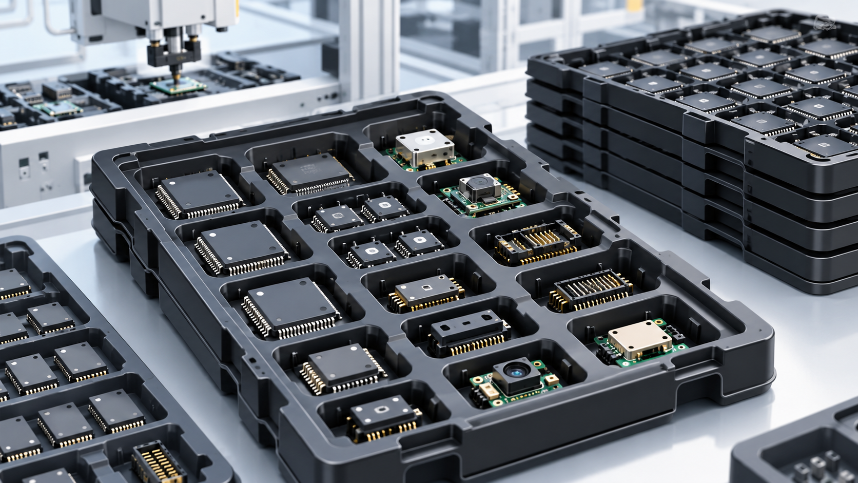
A thermoformed ESD tray does more than organize electronic components. It must protect sensitive devices from electrostatic discharge, control movement during handling and transport, maintain repeatable component orientation, and often interface directly with automated assembly or inspection equipment.
For electronics manufacturers, this makes an ESD thermoformed tray part of the production process—not simply disposable packaging.
For a broader overview of thermoformed trays, clamshells, blisters and other plastic packaging formats, see our Thermoformed Packaging Guide.
A successful tray therefore requires four elements to work together:
ESD material + component-specific cavity design + precision forming + efficient stacking or nesting
An ESD thermoformed tray is formed from plastic sheet engineered to control electrostatic charge while holding electronic parts in defined cavities.
Typical applications include:
Integrated circuits
Sensors
Connectors
PCB assemblies
Electronic modules
Optical components
Memory and storage components
Small precision electronic parts
The tray may be used during:
Manufacturing → Inspection → Work-in-Process Storage → Automated Assembly → Transportation
Unlike general-purpose packaging trays, ESD trays need to address both electrical protection and mechanical protection.
One of the most common mistakes in electronics packaging is treating the terms anti-static, static dissipative and conductive as interchangeable.
They describe different material behaviors.
Anti-static materials are generally intended to reduce charge generation when surfaces contact or separate.
They can be useful in certain handling applications, but the term alone does not define how quickly charge will dissipate or whether the material is appropriate for direct contact with a specific ESD-sensitive device.
Static dissipative materials allow charge to move in a controlled manner rather than remaining concentrated on the surface or discharging extremely rapidly.
This makes dissipative materials especially important for many applications where the tray directly contacts sensitive electronic components.
Conductive materials provide a lower-resistance path for charge movement.
They are used in many ESD-control applications, but lower resistance does not automatically mean better protection.
If a highly charged sensitive device suddenly contacts a very conductive surface, rapid discharge itself can become a risk.
The correct ESD specification should therefore come from the manufacturer's ESD control program rather than from simply requesting a “black conductive tray.”
Black plastic is commonly associated with conductive ESD packaging because carbon-based additives are frequently used in conductive compounds.
However:
Color alone does not prove ESD performance.
Likewise, a clear or colored tray should not automatically be assumed to be non-ESD.
The material specification should identify the required electrical characteristics and test method.
Common base polymers used for thermoformed electronics trays can include:
PET
PS / HIPS
ABS
PP
Specialty ESD compounds
The appropriate choice depends on:
Required surface resistance
Component sensitivity
Sheet thickness
Forming depth
Impact resistance
Transparency requirements
Temperature exposure
Reuse cycles
Chemical environment
For a wider comparison of thermoforming plastics, see MINGDU's Thermoforming Materials Guide.
ESD properties can be created in different ways.
Some sheets use additives or conductive components incorporated into the polymer. Others may use surface-applied anti-static treatments.
For reusable production trays, manufacturers should ask:
Is the ESD performance permanent or temporary?
Is performance affected by humidity?
Can abrasion reduce effectiveness?
Will repeated cleaning change surface resistance?
Has the finished thermoformed tray been tested, not only the original sheet?
This last question matters because forming, stretching, surface condition and processing can affect the final part.
For critical electronics applications, verify the finished tray, not merely the raw material certificate.
An ESD material does not protect a component from mechanical damage.
The cavity must also prevent unnecessary movement and contact with sensitive areas.
A good electronics tray should support the component at appropriate locations while avoiding excessive pressure on:
Pins
Leads
Connectors
Sensors
Optical surfaces
Solder joints
Delicate housings
The cavity should therefore be developed from an actual product drawing, CAD model or physical sample.
A cavity that matches the nominal component dimensions too closely can cause:
Difficult loading
Part sticking
Component scratching
Interference from product tolerances
Problems with robotic unloading
Too much clearance allows components to move inside the tray.
This can create:
Impact between part and cavity wall
Bent leads
Surface abrasion
Orientation errors
Pick-and-place inconsistency
The objective is controlled clearance, not simply the smallest possible cavity.
For manual handling, a small amount of positional variation may be acceptable.
For robotic pick-and-place systems, dimensional repeatability becomes much more important.
Automation may depend on predictable:
Cavity center position
Tray outer dimensions
Pocket depth
Component height
Orientation
Datum features
Trim edges
If the cavities shift from tray to tray, the robot may:
Miss the part
Grip it incorrectly
Trigger machine alarms
Require manual intervention
Reduce line efficiency
This is why electronics packaging thermoforming should be treated as a precision manufacturing process.
However, there is no single universal tolerance that every ESD tray must meet.
Required tolerances should be established from:
Component tolerance + tray material + forming shrinkage + automation accuracy + tooling capability
rather than copied from an unrelated tray design.
Many electronic components must enter an assembly line in one specific direction.
The tray can help control orientation through:
Asymmetric cavity geometry
Orientation notches
Corner features
Indexing marks
Dedicated pick locations
For automated systems, preventing incorrect loading at the packaging stage can be more effective than trying to detect incorrect orientation later.
The tray can therefore act as a simple poka-yoke, or error-prevention feature.
Both are important when designing thermoformed trays.
Nesting means empty trays fit partly inside one another.
This reduces:
Storage volume
Return-shipping volume
Warehouse space
Empty-tray handling
But excessive nesting can cause trays to lock together and become difficult to separate automatically.
Designers may therefore include features that control nesting depth.
Stacking means loaded trays sit safely on top of one another without damaging the components below.
A stackable tray may use:
Perimeter rails
Corner supports
Standoffs
Locating features
Interlocking geometry
The upper tray should transfer load through structural areas of the lower tray—not through the electronic components.
Reusable manufacturing trays often need to:
Nest when empty → Stack when loaded
This requirement should be included at the beginning of the tray design because it influences wall geometry, cavity layout and overall tray depth.
Efficient cavity layout affects both packaging cost and factory logistics.
Important variables include:
Number of components per tray
Cavity pitch
Robot access
Component clearance
Tray dimensions
Carton dimensions
Production batch size
Increasing cavity count may reduce packaging cost per component, but very dense layouts can create problems with:
Automated picking
Wall thickness
Tool venting
Tray stiffness
Component loading
The best layout is therefore not necessarily the one with the maximum number of cavities.
It is the layout that fits the manufacturing workflow.
If trays will feed automated equipment, package engineers should involve automation engineers before tooling is finalized.
Review:
Can the robot gripper, nozzle or vacuum head reach the component without contacting the cavity walls?
Does every component sit at a repeatable height and orientation?
How does the machine locate the tray?
Possible references include:
Outer edges
Holes
Notches
Corners
Dedicated datum features
If empty trays are automatically separated, can the system reliably lift one tray at a time?
A tray that flexes significantly during handling may reduce positioning accuracy even when cavity dimensions are correct.
For highly detailed tray geometry, a Pressure Forming Machine can be evaluated when greater definition or controlled forming is required.
Thin-gauge ESD trays are formed by stretching heated sheet into multiple cavities.
The starting sheet thickness therefore does not remain uniform throughout the tray.
Thinner areas can develop around:
Deep cavity walls
Bottom corners
Narrow ribs
Sharp transitions
High draw areas
This can influence:
Tray stiffness
Reusability
Component protection
Dimensional stability
Simply increasing starting sheet thickness is not always the best solution.
Engineers should also review:
Draw depth
Corner radius
Cavity spacing
Heating profile
Mold geometry
Forming method
For high-volume electronic tray production, MINGDU's Thin-Gauge Thermoforming Machines can be evaluated according to sheet specification, tray dimensions, cavity layout and target output.
A typical process is:
ESD Sheet → Heating → Forming → Cooling → Trimming → Electrical Testing → Dimensional Inspection
Confirm:
Polymer
ESD classification
Sheet thickness
Surface condition
Supplier documentation
The sheet is heated to a suitable forming condition.
Uneven heating can produce uneven material distribution and dimensional variation.
Vacuum, pressure or combined forming methods shape the sheet against the mold.
The required method depends on cavity depth, detail and material.
The tray must cool sufficiently to stabilize before removal.
Poor cooling control can contribute to:
Warpage
Shrinkage variation
Dimensional instability
The finished tray is cut from the surrounding web.
Trim consistency is especially important when automated equipment uses the tray edge as a locating datum.
Where ESD performance is critical, the finished tray should be tested according to the required specification and test method.
Critical dimensions may include:
Cavity location
Cavity depth
Tray width and length
Stack height
Datum locations
Component seating height
The inspection plan should be based on the actual handling and automation requirements.
An ESD tray can meet an electrical specification and still fail as packaging.
For example:
Correct resistance + poor cavity fit
→ component movement and mechanical damage
Good cavity fit + unsuitable ESD material
→ static-control risk
Good tray + poor stacking design
→ components damaged by the tray above
Precise cavities + inconsistent trim
→ robotic handling problems
A successful electronics tray therefore needs:
Electrical protection + mechanical protection + dimensional control + process compatibility
The intended number of handling cycles should influence tray design.
Priorities may include:
Lower material consumption
Lightweight construction
Efficient nesting
Lower unit cost
Priorities may shift toward:
Increased stiffness
Durable ESD performance
Repeated stacking
Cleaning resistance
Dimensional stability
Robotic handling
A reusable tray may cost more initially but provide lower cost per use in a closed-loop manufacturing system.
The correct choice should be based on actual logistics rather than simply making the tray as thick as possible.
Before approving a tray design, confirm:
| Area | Key Question |
|---|---|
| ESD performance | What electrical property does the application require? |
| Material | Is the ESD property permanent and suitable for the environment? |
| Component fit | Are sensitive pins and surfaces protected? |
| Clearance | Can parts be loaded and removed reliably? |
| Precision | Are cavity positions repeatable enough for automation? |
| Orientation | Can the component be loaded incorrectly? |
| Nesting | Can empty trays separate reliably? |
| Stacking | Are loaded components protected from the tray above? |
| Rigidity | Does tray flex affect handling accuracy? |
| Trimming | Can automated equipment locate the tray consistently? |
| Inspection | Are ESD and dimensional requirements verified on finished parts? |
ESD thermoformed trays can use PET, PS/HIPS, ABS, PP and specialty compounds with anti-static, static-dissipative or conductive properties. The correct material depends on the required ESD performance, mechanical properties and manufacturing environment.
Not necessarily. “Anti-static” generally describes reduced charge generation, while an ESD-control requirement may also specify static-dissipative or conductive electrical properties. The packaging specification should define the required performance.
They provide custom cavities that organize, position and physically protect components while ESD-grade materials can provide the required static-control properties.
Yes. Custom thermoformed trays can be designed with repeatable cavity locations, orientation features, controlled component height and tray datums for automated handling.
Nesting allows empty trays to fit inside one another to save space. Stacking allows loaded trays to sit on top of one another while protecting the components inside.
For applications with defined ESD requirements, finished-part verification is advisable because the final tray—not only the raw sheet—is what contacts and protects the electronic component.
A successful ESD thermoformed tray is not simply a plastic tray made from conductive material.
It needs to control electrostatic risk while also supporting the physical and dimensional requirements of electronics manufacturing.
The most important design decisions are:
Select the correct ESD material specification.
Protect sensitive component features.
Control cavity position and component orientation.
Design nesting and stacking deliberately.
Maintain sufficient tray rigidity and wall thickness.
Match dimensional tolerances to the automation system.
Verify electrical and dimensional performance on the finished tray.
For high-volume electronics packaging, MINGDU's Thin-Gauge Thermoforming Machines can be evaluated for thin-sheet tray production, while Pressure Forming Machines can be considered where package geometry requires greater forming definition.
The machine, material, mold and tray design should ultimately be developed around the electronic component and the way that component moves through the production line.


